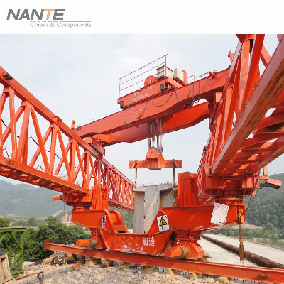
300T Beam Launcher for Bridge & Viaducts Construction Product
Description A launching gantry (also called beam
launcher, girder launcher,[bridge building crane, and
bridge-building machine, locally nicknamed the "Iron Monster") is a
special-purpose mobile gantry crane used in bridge construction,
specifically segmental bridges that use precast box girder bridge
segments or precast girders in highway and high-speed rail bridge
construction projects. The launching gantry is used to lift and
support bridge segments or girders as they are placed while being
supported by the bridge piers instead of the ground.
While superficially similar, launching gantry machines
should not be confused with movable scaffolding systems, which also
are used in segmental bridge construction. Both feature long
girders spanning multiple bridge spans which move with the work,
but launching gantry machines are used to lift and support precast
bridge segments and bridge girders, while movable scaffolding
systems are used for cast-in-place construction of bridge
segments. Typically, precast segmental bridges
and precast girders are placed using ground-based cranes to lift
each segment or girder. However, ground access to the spans may be
challenged by the presence of existing infrastructure or bodies of
water or the height to which the segments must be raised can exceed
the reach of ground-based cranes. A launching gantry can be used to
solve these issues. The most visible feature of a
launching gantry are the twin parallel girders which can either be
above (upper-beam) or below (lower-beam or underslung) the bridge
deck. However, a single beam can also be used, typically in
upper-beam configuration. The launching gantry machine usually is
sized to the construction project, with the length of the twin main
girders approximately 2.3 times the distance between spans. This
length enables the launching gantry to span the gap between two
adjacent bridge piers while providing allowances for the distance
required for launching to the next span and flexibility of movement
to accommodate curved paths between piers. In some cases, hinges
have been inserted into the gantry girders to allow tighter curves.
The launching gantry girders are supported at each pier by braced
frames which have a limited range of movement to facilitate
placement of bridge segments or bridge girders; the launching
gantry does not generally contact the bridge deck.
Two gantry trolleys can run the full length of the
launching gantry girders. Each trolley is equipped with two
winches: a main winch to suspend the load, and a translation winch
to move the trolley along the girders. When bridge segments (or
bridge girders) are delivered at the ground level, the launching
gantry is used to pick them up and raise them to deck or pier
height. If the segments (or girders) are delivered instead at the
bridge deck level, the launching gantry moves back to allow the
forward trolley to pick up the front end of the next segment (or
girder), while the back end of the segment (or girder) is supported
by the transportation vehicle; as the forward trolley moves
forward, the rear trolley takes over supporting the back end from
the vehicle. Bridge segments (or bridge girders)
are set in place by the launching gantry until the span between
adjacent piers is completed. For segmental bridges, typically a
span-by-span or balanced-cantilever approach is adopted to place
segments. To free up the gantry trolley(s), temporary hangers are
used to support each segment after it has been placed. In the
span-by-span approach, all the segments for a span are placed
before bridge tendons are tensioned; in this fashion, work
progresses from one pier towards an adjacent pier. In the
balanced-cantilever approach, segments are placed simultaneously on
each side and work progresses from a central pier towards the two
nearest piers instead. In either case, the launching gantry girders
and hangers essentially serve as false work prior to
tensioning. Once the bridge span between adjacent
piers is completed, the winches on the trolleys are used to lift
the gantry girders and "launch" them ahead to the next span. The
process of lifting and placing bridge segments (or girders)
followed by launching the gantry girders ahead is repeated until
the bridge is complete. Launching gantries are
often distinguished by the design of the main girders.Honeycomb
Girder: The honeycomb girder launching
gantry has been proven suitable to a lifting range of 5 to
300t. The main girder of a honeycomb girder is
fabricated from welded plates, forming an isosceles triangle
cross-section. Regular hexagonal holes are cut in the inclined web
plates to reduce wind resistance. Because the honeycomb girder is
formed by relatively long seam welds joining plates, the welds will
not lose integrity easily due to small welding defects.Truss
Girder:The main girder of a truss girder is fabricated from welded
steel poles.
Quality 300t Beam Launcher for Bridge & Viaducts Construction products, provide good price 300t Beam Launcher for Bridge & Viaducts Construction from .
Larger photo of 300t Beam Launcher for Bridge & Viaducts Construction
Related products about 300t Beam Launcher for Bridge & Viaducts Construction
-
 Waste Tyre Plastic Recycling Machinery Machine Tire Crusher Production Line Rubber Crumb Grinding Machine Equipment Tire Shredder
-
 Stretch Plastic Blowing Pet Bottle Making Blow Molding Machine Bottles Stretch Automatic Pet Bottle Blowing Machine
-
 Waste Plastic Pet Bottle, Water Bottle Flake, PP/HDPE/LDPE PE Film Jumbo Woven Bags Plastic Crusher Machine, Plastic Crushing Washing Recycling Machine
-
 Type 2 Wall-Mounted Electric Car Charging Station 7kw /11 Kwelectric Vehicle Charging Station Home Wallbox AC EV Charger Single Phase or 3three Phase
-
 G-View G12W Wholesale Auto Car LED Headlight Bulb High Power H13 H11 9005 H7 H4 Car LED Headlights LED Car Lights
-
 New Design Porcelain Round Plates Dinner Set for Wedding and Banquet
-
 China 2023 New Design Super Soft 100% Polyester Microfiber Knitted Oversized Decoration Hoodie Blanket
-
 Handmade Art Creative Materials Thickened White Paper Cup DIY Disposable Handmade Colored Paper Cup


